|
Oil Interceptor DESIGN and OPERATION: The designs of Based on this design criterion, most of the suspended solids will settle to the bottom of the separator as a sediment layer, the oil will rise to top of the separator, and the wastewater will be the middle layer between the oil on top and the solids on the bottom. In an installed trap 1/8” above the static water level is an adjustable draw off valve. This valve skims the oil rising to the surface inside of the interceptor. This oil is drawn off to a separate holding tank. The bucket, which retains solid material, needs to be lifted out of the interceptor for emptying at appropriate intervals. Interceptors should not be located directly in traffic areas. If required, specify extra heavy duty traffic cover. The manufacturing process adheres to Canadian standard CAN/CSA-B481 SERIES-07. DESCRIPTION ALPINE Oil Interceptor is coated inside and outside fabricated steel with required rating. Unit shall include sediment bucket made of Stainless steel, deep seal trap, secured and removable cover, adjustable automatic draw-off assembly, 2” double vent connections, The Units are used where spillages of oil or diesel could occur, to help prevent the pollution of rivers, streams, drainage systems and water treatment plants., horizontal inlet/outlet, 2” adjustable draw off inlet. |

|
|
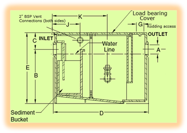
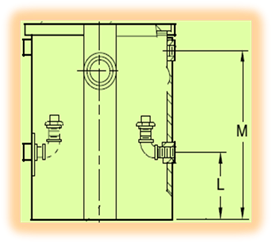
DIAGRAM OF ALPINE OIL INTERCEPTOR
(Since the dimensions and other parameters are subject to change without notice;
Therefore, always please refer to technical offer)
|
INSTALLATION and MAINTENANCE This unit should be installed so that the inlet receives the incoming drain line and the outlet dumps into the outgoing drain line. The draw off valve should be connected to a holding tank to receive the waste oil.
|
||||||||||
|
SIZING FOR ALPINE OIL INTECEPTOR
Steps to size the Oil Interceptor 1. Estimate the peak volume of waste water [see note i] either in litres /sec. or gallon/min. (1) Covered Area (B) Sizing for Oil Storage Tank
|
OIL HOVER: |
||||||||||
|
|||||||||||